Measurement of Resistance
Resistance is one of the most basic elements encountered in electrical and electronics engineering. The value of resistance in engineering varies from very small value like, resistance of a transformer winding, to very high values like, insulation resistance of that same transformer winding. Although a multimeter works quite well if we need a rough value of resistance, but for accurate values and that too at very low and very high values we need specific methods. In this article we will discuss various methods of resistance measurement. For this purpose we categories the resistance into three classes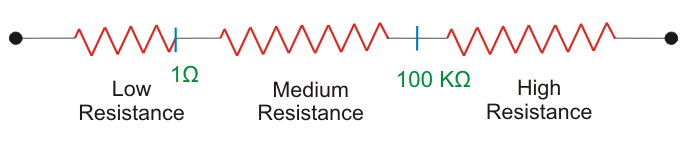 Measurement of Low Resistance (<1Ω)
Measurement of Low Resistance (<1Ω)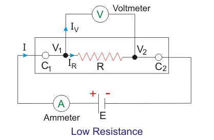
The current is flown through current terminals C1 and C2 while the potential drop is measured across potential terminals V1 and V2. Hence we can find out the value of resistance under experiment in terms of V and I as indicated in the above figure. This method helps us to exclude the contact resistance due to current terminals and though contact resistance of potential terminals still comes into picture, it is very small fraction of high resistance potential circuit and hence induces negligible error.
The methods employed for measurement of low resistances are:-
- Kelvin’s Double Bridge Method
- Potentiometer Method
- Ducter Ohmmeter.
Kelvin’s Double Bridge
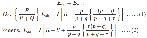
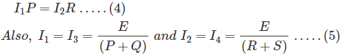
Kelvin’s double bridge is a modification of simple Wheatstone bridge. Figure below shows the circuit diagram of Kelvin’s double bridge.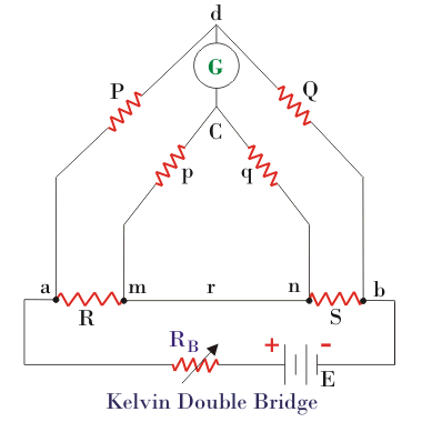 As we can see in the above figure there are two sets of arms, one with resistances P and Q and other with resistances p and q. R is the unknown low resistance and S is a standard resistance. Here r represents the contact resistance between the unknown resistance and the standard resistance, whose effect we need to eliminate. For measurement we make the ratio P/Q equal to p/q and hence a balanced Wheatstone bridge is formed leading to null deflection in the galvanometer. Hence for a balanced bridge we can write
 Putting eqn 2 in 1 and solving and using P/Q = p/q, we get-
 Hence we see that by using balanced double arms we can eliminate the contact resistance completely and hence error due to it. To eliminate another error caused due to thermo-electric emf, we take another reading with battery connection reversed and finally take average of the two readings. This bridge is useful for resistances in range of 0.1µΩ to 1.0 Ω.
Ducter Ohmmeter
It is an electromechanical instrument used for measurement of low resistances. It comprises of a permanent magnet similar to that of a PMMC instrument and two coils in between the magnetic field created by the poles of the magnet. The two coils are at right angles to each other and are free to rotate about the common axis. Figure below shows a Ducter Ohmmeter and the connections required to measure an unknown resistance R.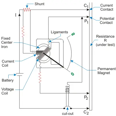 One of the coil called current coil, is connected to current terminals C1 and C2, while the other coil called, voltage coil is connected to potential terminals V1 and V2. Voltage coil carries current proportional of the voltage drop across R and so is its torque produced. Current coil carries current proportional to the current flowing through R and so is its torque too. Both the torque acts in opposite direction and the indicator come to halt when the two are equal. This instrument is useful for resistance in range 100µΩ to 5Ω.
Measurement of Medium Resistance (1Ω - 100kΩ)
Following are the methods employed for measuring a resistance whose value is in the range 1Ω - 100kΩ -- Ammeter-Voltmeter Method
- Wheatstone Bridge Method
- Substitution Method
- Carey- Foster Bridge Method
- Ohmmeter Method
Ammeter Voltmeter Method
This is the most crude and simplest method of measuring resistance. It uses one ammeter to measure current, I and one voltmeter to measure voltage, V and we get the value of resistance as Now we can have two possible connections of ammeter and voltmeter, shown in the figure below.
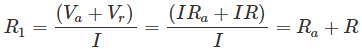
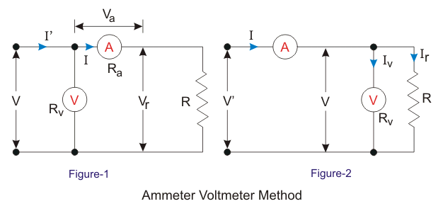 Now in figure 1, the voltmeter measures voltage drop across ammeter and the unknown resistance, hence
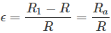
 Hence, the relative error will be,
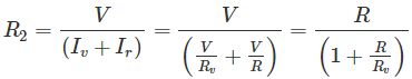
 For connection in figure 2, the ammeter measures the sum of current through voltmeter and resistance, hence
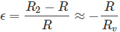
 The relative error will be,
 It can be observed that the relative error is zero for Ra = 0 in first case and Rv = ∞ in second case. Now the questions stand that which connection to be used in which case. To find out this we equate both the errors
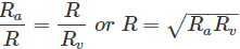 Hence for resistances greater than that given by above equation we use the first method and for less than that we use second method.
Wheatstone Bridge Method
This is the simplest and the most basic bridge circuit used in measurement studies. It mainly consists of four arms of resistance P, Q; R and S. R is the unknown resistance under experiment, while S is a standard resistance. P and Q are known as the ratio arms. An EMF source is connected between points a and b while a galvanometer is connected between points c and d.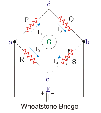 A bridge circuit always works on the principle of null detection, i.e. we vary a parameter until the detector shows zero and then use a mathematical relation to determine the unknown in terms of varying parameter and other constants. Here also the standard resistance, S is varied in order to obtain null deflection in the galvanometer. This null deflection implies no current from point c to d, which implies that potential of point c and d is same. Hence
 Combining the above two equations we get the famous equation –

Substitution Method
The figure below shows the circuit diagram for resistance measurement of an unknown resistance R. S is a standard variable resistance and r is a regulating resistance.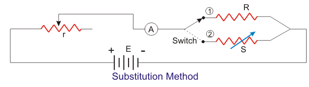 First the switch is place at position 1 and the ammeter is made to read a certain amount of current by varying r. The value of ammeter reading is noted. Now the switch is moved to position 2 and S is varied in order to achieve the same ammeter reading as it read in the initial case. The value of S for which ammeter reads same as in position 1, is the value of unknown resistance R, provided the EMF source has constant value throughout the experiment.
Measurement of High Resistance (>100kΩ)
Following are few methods used for measurement of high resistance values-- Loss of Charge Method
- Megger
- Megohm bridge Method
- Direct Deflection Method
- Electrostatic charges can get accumulated on measuring instruments
- Leakage current becomes comparable to measuring current and can cause error
- Insulation resistance is one of the most common in this category; however a dielectric is always modeled as a resistor and capacitor in parallel. Hence while measuring the insulation resistance (I.R.) the current includes both the component and hence true value of resistance is not obtained. The capacitive component though falls exponentially but still takes very long time to decay. Hence different values of I.R. are obtained at different times.
- Protection of delicate instruments from high fields.
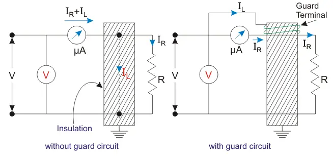 In the first circuit the micro ammeter measures both capacitive and the resistive current leading to error in value of R, while in the other circuit the micro ammeter reads only the resistive current.
Loss of Charge Method
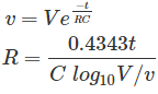
In this method we utilize the equation of voltage across a discharging capacitor to find the value of unknown resistance R. Figure below shows the circuit diagram and the equations involved are-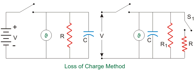
 However the above case assumes no leakage resistance of the capacitor. Hence to account for it we use the circuit shown in the figure below. R1 is the leakage resistance of C and R is the unknown resistance.
We follow the same procedure but first with switch S1 closed and next with switch S1 open. For the first case we get
However the above case assumes no leakage resistance of the capacitor. Hence to account for it we use the circuit shown in the figure below. R1 is the leakage resistance of C and R is the unknown resistance.
We follow the same procedure but first with switch S1 closed and next with switch S1 open. For the first case we get
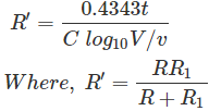 For second case with switch open we get
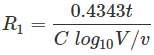 Using R1 from above equation in equation for R’ we can find R.
Megohm Bridge Method
In this method we use the famous Wheatstone bridge philosophy but in a slightly modified way. A high resistance is represented as in the figure below.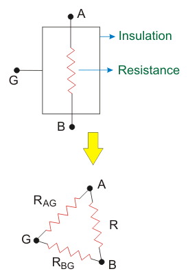 G is the guard terminal. Now we can also represent the resistor as shown in the adjoining figure, where RAG and RBG are the leakage resistances. The circuit for measurement is shown in the figure below.
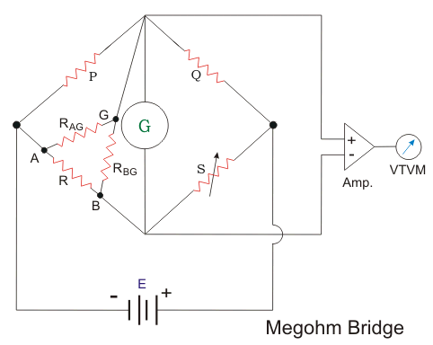 It can be observed that we actually obtain the resistance which is parallel combination of R and RAG. Although this causes very insignificant error.
 Where, Fm1 and Fm2 are respectively the maximum values of fluxes F1 and F2, B is phase difference between two fluxes.
We can also write the expression for induced emf's at point one be
Where, Fm1 and Fm2 are respectively the maximum values of fluxes F1 and F2, B is phase difference between two fluxes.
We can also write the expression for induced emf's at point one be

 Where, K is some constant and f is frequency.
Let us draw phasor diagram clearly showing F1, F2, E1, E2, I1 and I2. From phasor diagram, it clear that I1 and I2 are respectively lagging behind E1 and E2 by angle A.
Where, K is some constant and f is frequency.
Let us draw phasor diagram clearly showing F1, F2, E1, E2, I1 and I2. From phasor diagram, it clear that I1 and I2 are respectively lagging behind E1 and E2 by angle A.
 The angle between F1 and F2 is B. From the phasor diagram the angle between F2 and I1 is (90-B+A) and the angle between F1 and I2 is (90 + B + A). Thus we write the expression for deflecting torque as
 Similarly the expression for Td2 is,
 The total torque is Td1 - Td2, on substituting the the value of Td1 and Td2 and simplying the expression we get
 Which is known as the general expression for the deflecting torque in the induction type meters. Now there are two types of induction meters and they are written as follows:
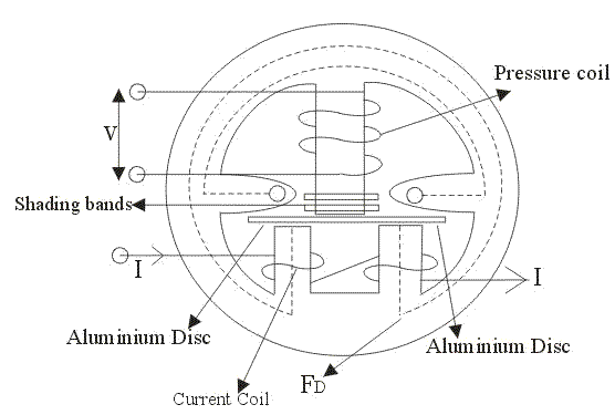 Single phase induction type energy meter consists of four important systems which are written as follows:
 Here we have assumed that the pressure coil is highly inductive in nature and consists of very large number of turns. The current flowin in the pressure coil is Ip which lags behind voltage by an angle of 90 degrees. This current produces flux F. F is divided into two parts Fg and Fp.
 Let us again consider the same circuit but the difference is here we are using the practical rectifying element instead of ideal one. Practical rectifying element is having some finite forward blocking voltage and high reverse blocking voltage. We will apply the same procedure in order to obtain the voltage current characteristics of practical rectifying element. Now when we make the practical rectifying element forward biased it does not conduct till the applied voltage is not greater the forward breakdown voltage or we can say knee voltage. When the applied voltage becomes greater than the knee voltage then diode or rectifying element will come under conduction mode. Thus behaves as short circuited but due to some electrical resistance there is voltage drop across this practical diode. We can make the rectifying element forward biased by connecting the positive terminal of the battery with anode and negative terminal with cathode. The forward characteristic of practical rectifying element or diode is shown in the voltage current characteristic. Now when we apply negative voltage i.e. connecting the negative terminal of the battery with the anode terminal of the diode and positive terminal of the battery to the cathode terminal of the rectifying element. Due to reverse biased it offers finite resistance and the negative voltage till the applied voltage becomes equal to reverse break down voltage and thus it behaves as open circuit. The complete characteristics are shown below
 Now rectifier type of instruments uses two types of rectifier circuits:
 The function of this multiplier electrical resistance is to limit the current drawn by the permanent magnet moving coil type of instrument. It is very essential to limit the current drawn by the permanent magnet moving coil instrument because if the current exceeds the current rating of PMMC then it destructs the instrument. Now here we divide our operation in two parts. In first part we apply constant DC voltage to the above circuit. In the circuit diagram we are assuming the rectifying element as ideal one. Let us mark the resistance of multiplier be R, and that of permanent magnet moving coil instrument be R1. The DC voltage produces a full scale deflection of magnitude I=V/(R+R1) where V is root mean square value of voltage. Now let us consider second case, in this case we will apply AC sinusoidal AC voltage to the circuit v =Vm × sin(wt) and we will get the output waveform as shown. In the positive half cycle the rectifying element will conduct and in the negative half cycle it does not conduct. So we will get a pulse of voltage at moving coil instrument which produces pulsating current thus pulsating current will produce pulsating torque. The deflection produced will corresponds to the average value of voltage. So let us calculate the average value of electric current, in order to calculate the average value of voltage we have integrate the instantaneous expression of the voltage from 0 to 2 pi. So the calculated average value of voltage comes out to be 0.45V. Again we have V is root mean square value of current. Thus we conclude that the sensitivity of the ac input is 0.45 times the sensitivity of DC input in case of half wave rectifier.
 We have used here a bridge rectifier circuit as shown. Again we divide our operation into two parts. In the first we analyze the output by applying the DC voltage and in another we will apply AC voltage to the circuit. A series multiplier resistance is connected in series with the voltage source which has the same function as described above. Let us consider first case here we applying DC voltage source to the circuit. Now the value of full scale deflection current in this case is again V/(R+R1), where V is the root mean square value of the applied voltage, R is the resistance of the resistance multiplier and R1 which is the electrical resistance of the instrument. The R and R1 are marked in the circuit diagram. Now let us consider second case, in this case we will apply AC sinusoidal voltage to the circuit which is given v = Vmsin(wt) where Vm is the peak value of the applied voltage again if we calculate the value of full scale deflection current in this case by applying the similar procedure then we will get an expression of full scale current as .9V/(R+R1). Remember in order to obtain the average value of voltage we should integrate the instantaneous expression of voltage from zero to pi. Thus comparing it DC output we conclude that the sensitivity with AC input voltage source is 0.9 times the as in the case of DC input voltage source.
 The output wave is shown below. Now we are going to discuss the factors which affect the performance of Rectifier type instruments:

 From this value of electric current the input energy can be calculated as

 By neglecting the higher order terms that appears in the expression. Now applying the principle of energy conservation we have input energy to the system = increase in the stored energy of the system + mechanical work done by the system. From this we can write,
 From the above equation the force can be calculated as
 Now let us derive force and torque equation for the rotary electrostatic type instruments. Diagram is shown below,
 In order to find out the expression for deflecting torque in case of rotary type electrostatic instruments, just replace the in the equation (1) F by Td and dx by dA. Now rewriting the modified equation we have deflecting torque is equals to
 Now at steady state we have controlling torque is given by the expression Tc = K × A. The deflection A can be written as
 From this expression we conclude that the deflection of the pointer is directly proportional to the square of the voltage to be measured hence the scale will be non uniform. Let us now discuss about Quadrant electrometer. This instrument is generally used in measuring the voltage ranging from 100V to 20 kilo volts. Again the deflecting torque obtained in the Quadrant electrometer is directly proportional to the square of the applied voltage; one advantage of this is that this instrument can used to measure both the AC and DC voltages. One advantage of using the electrostatic type instruments as voltmeters is that we can extend the range of voltage to be measured. Now there are two ways of extending the range of this instrument. We will discuss them one by one.
 The voltage which we want to measure is applied across the total resistance r and the electrostatic capacitor is connected across the portion of the total resistance which is marked as r. Now suppose the applied voltage is DC, then we should make one assumption that the capacitor which is connected is having infinite leakage resistance. In this case the multiplying factor is given by the ratio of electrical resistance r/R. The ac operation on this circuit can also be analyzed easily again in case of ac operation we multiplying factor equal to r/R.
(b) By using capacitor multiplier technique: We can increase the range of voltage to be measured by placing a series of capacitors as shown in the given circuit.
The voltage which we want to measure is applied across the total resistance r and the electrostatic capacitor is connected across the portion of the total resistance which is marked as r. Now suppose the applied voltage is DC, then we should make one assumption that the capacitor which is connected is having infinite leakage resistance. In this case the multiplying factor is given by the ratio of electrical resistance r/R. The ac operation on this circuit can also be analyzed easily again in case of ac operation we multiplying factor equal to r/R.
(b) By using capacitor multiplier technique: We can increase the range of voltage to be measured by placing a series of capacitors as shown in the given circuit.
 Let us derive the expression for multiplying factor for the circuit diagram 1. Let us mark the capacitance of the voltmeter be C1 and series capacitor be C2 as shown in the given circuit diagram. Now the series combination of these capacitor be equal to
 Which is the total capacitance of the circuit. Now the impedance of the voltmeter is equal to Z1 = 1/jωC1 and thus total impedance will be equal to
 Now the multiplying factor can be defined as the ratio of Z/Z1 which is equal to 1 + C2 / C1. Similarly the multiplying factor can also be calculated. Hence by this way we can increase the range of voltage to be measure.
