Saturday, November 24, 2018

Moving iron type instruments

This instrument is one of the most primitive forms of measuring and relay instrument. Moving iron type instruments are of mainly two types. Attraction type and repulsion type instrument.
Whenever a piece of iron is placed nearer to a magnet it would be attracted by the magnet. The force of this attraction depends upon the strength said magnetic field. If the magnet is electromagnet then the magnetic field strength can easily be increased or decreased by increasing or decreasing current through its coil. Accordingly the attraction force acting on the piece of iron would also be increased and decreased. Depending upon this simple phenomenon attraction type moving iron instrument was developed.
Whenever two pieces of iron are kept side by side and a magnet is brought nearer to them the iron pieces will repulse each other. This repulsion force is due to same magnetic poles induced in same sides the iron pieces due external magnetic field. This repulsion force increases if field strength of the magnet is increased. Like case if the magnet is electromagnet, then magnetic field strength can easily be controlled by controlling input current to the magnet. Hence if the current increases the repulsion force between the pieces of iron is increased and it the current decreases the repulsion force between them is decreased. Depending upon this phenomenon repulsion type moving iron instrument was constructed.

Construction of Moving Iron Instrument

attraction-moving-iron-instrument
The basic construction of attraction type moving iron instrument is illustrated bellow A thin disc of soft iron is eccentrically pivoted in front of a coil. This iron tends to move inward that is from weaker magnetic field to stronger magnetic field when current flowing through the coil. In attraction moving instrument gravity control was used previously but now gravity control method is replaced by spring control in relatively modern instrument. By adjusting balance weight null deflection of the pointer is achieved. The required damping force is provided in this instrument by air friction. The figure shows a typical type of damping system provided in the instrument, where damping is achieved by a moving piston in an air syringe.
Theory of Attraction Type Moving Iron Instrument
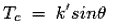
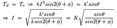
Suppose when there is no current through the coil, the pointer is at zero, the angle made by the axis of the iron disc with the line perpendicular to the field is φ. Now due current I and corresponding magnetic field strength, the iron piece is deflected to an angle θ. Now component of H in the direction of defected iron disc axis is Hcos{90 - (θ + φ) or Hsin (θ + φ). Now force F acting on the disc inward to the coil is thus proportional to H2sin(θ + φ) hence the force is also proportional to I2sin(θ + φ) for constant permeability. If this force is acting on the disc at a distance l from the pivot, then deflection torque, working of moving iron instrument Since l is constant. Where, k is constant. Now, as the instrument is gravity controlled, controlling torque will be Where, k' is constant. At steady state condition, Where, K is constant.
Permanent Magnet Moving Coil Instrument

The permanent magnet moving coil instrument or PMMC type instrument uses two permanent magnets in order to create stationary magnetic field. These types of instruments are only used for measuring the DC quantities as if we apply AC current to these type of instruments the direction of current will be reversed during negative half cycle and hence the direction of torque will also be reversed which gives average value of torque zero. The pointer will not deflect due to high frequency from its mean position showing zero reading. However it can measure the direct current very accurately.
Let us move towards the constructions of permanent magnet moving coil instruments. We will see the construction of these types of instruments in five parts and they are described below: pmmc permanent magnet moving coil instrument
  • Stationary Part or Magnet System: In the present time we use magnets of high field intensities, high coercive force instead of using U shaped permanent magnet having soft iron pole pieces. The magnets which we are using nowadays are made up of materials like alcomax and alnico which provide high field strength.
  • Moving Coil: The moving coil can freely moves between the two permanent magnets as shown in the figure given below. The coil is wound with many turns of copper wire and is placed on rectangular aluminium which is pivoted on jeweled bearings.
  • Control System: The spring generally acts as control system for PMMC instruments. The spring also serves another important function by providing the path to lead current in and out of the coil.
  • Damping System: The damping force hence torque is provided by movement of aluminium former in the magnetic field created by the permanent magnets.
  • Meter: Meter of these instruments consists of light weight pointer to have free movement and scale which is linear or uniform and varies with angle.
Let us derive a general expression for torque in permanent magnet moving coil instruments or PMMC instruments. We know that in moving coil instruments the deflecting torque is given by the expression: Td = NBldI where N is number of turns, B is magnetic flux density in air gap, l is the length of moving coil, d is the width of the moving coil, And I is the electric current. Now for a moving coil instruments deflecting torque should be proportional to current, mathematically we can write Td = GI. Thus on comparing we say G = NBIdl. At steady state we have both the controlling and deflecting torques are equal. Tc is controlling torque, on equating controlling torque with deflection torque we have GI = K.x where x is deflection thus current is given by Since the deflection is directly proportional to the current therefore we need a uniform scale on the meter for measurement of current. Now we are going to discuss about the basic circuit diagram of the ammeter. Let us consider a circuit as shown below: basic ammeter The current I is shown which breaks into two components at the point A. The two components are Is and Im. Before I comment on the magnitude values of these currents, let us know more about the construction of shunt resistance. The basic properties of shunt resistance are written below, The electrical resistance of these shunts should not differ at higher temperature, it they should posses very low value of temperature coefficient. Also the resistance should be time independent. Last and the most important property they should posses is that they should be able to carry high value of current without much rise in temperature. Usually manganin is used for making DC resistance. Thus we can say that the value of Is much greater than the value of Im as resistance of shunt is low. From the we have, Where, Rs is resistance of shunt and Rm is the electrical resistance of the coil. From the above two equations we can write, Where, m is the magnifying power of the shunt.

Errors in Permanent Magnet Moving Coil Instruments

There are three main types of errors:
  1. Errors due to permanent magnets: Due to temperature effects and aging of the magnets the magnet may lose their magnetism to some extent. The magnets are generally aged by the heat and vibration treatment.
  2. Error may appear in PMMC Instrument due to the aging of the spring. However the error caused by the aging of the spring and the errors caused due to permanent magnet are opposite to each other, hence both the errors are compensated with each other.
  3. Change in the resistance of the moving coil with the temperature: Generally the temperature coefficients of the value of coefficient of copper wire in moving coil is 0.04 per degree celsius rise in temperature. Due to lower value of temperature coefficient the temperature rises at faster rate and hence the resistance increases. Due to this significant amount of error is caused.

Advantages of Permanent Magnet Moving Coil Instruments

  1. The scale is uniformly divided as the current is directly proportional to deflection of the pointer. Hence it is very easy to measure quantities from these instruments.
  2. Power consumption is also very low in these types of instruments.
  3. Higher value of torque is to weight ratio.
  4. These are having multiple advantages, a single instrument can be used for measuring various quantities by using different values of shunts and multipliers.
Instead of various advantages the permanent magnet moving coil instruments or PMMC Instrument posses few disadvantages.

Disadvantages of Permanent Magnet Moving Coil Instruments

  1. These instruments cannot measure ac quantities.
  2. Cost of these instruments is high as compared to moving iron instruments.

Errors in Measurement | Classification of Errors

In order to understand the concept of errors in measurement, we should know the two terms that defines the error and these two terms are written below:

True Value

It is not possible to determine the true value of a quantity by experiment means. True value may be defined as the average value of an infinite number of measured values when average deviation due to various contributing factor will approach to zero.

Measured Value

It may be defined as the approximated value of true value. It can be found out by taking means of several measured readings during an experiment, by applying suitable approximations on physical conditions.
Now we are in a position to define static error. Static error is defined as the difference of the measured value and the true value of the quantity. Mathematically we can write an expression of error as, dA = Am - At where, dA is the static error Am is measured value and At is true value. It may be noted that the absolute value of error cannot be determined as due to the fact that the true value of quantity cannot be determined accurately. Let us consider few terms related to errors.

Limiting Errors or Guarantee Errors

The concept of guarantee errors can be cleared if we study this kind of error by considering one example. Suppose there is a manufacturer who manufactures an ammeter, now he should promise or declare that the error in the ammeter that he is selling is not greater than the limit he sets. This limit of error is known as limiting errors or guarantee error.

Relative Error or Fractional Error

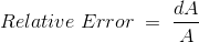
It is defined as the ratio of the error and the specified magnitude of the quantity. Mathematically we write as, Where, dA is the error and A is the magnitude. Now here we are interested in computing resultant limiting error under the following cases:
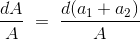
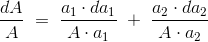
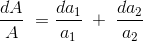
(a) By taking the sum of two quantities: Let us consider two measured quantities a1 and a2. The sum of these two quantities can be represented by A. Thus we can write A = a1 + a2. Now the relative incremental value of this function can be calculated as Separating the each term as shown below and by multiplying and dividing a1 with the first term and a2 with the second term we have From the above equation we can see that the resultant limiting error is equal to the sum of products formed by multiplying the individual relative limiting errors by the ratio of each term to the function. Same procedure can be applied to calculate the resultant limiting error due to summation of more than two quantities. In order to calculate the resultant limiting error due to difference of the two quantities just change the addition sign with subtraction and rest procedure is same. (b) By taking the product of two quantities: Let us consider two quantities a1 and a2. In this case the product of the two quantities are expressed as A = a1.a2. Now taking log both sides and differentiating with respect to A we have resultant limiting errors as From this equation we can see that the resultant error is summation of relative errors in measurement of terms. Similarly we can calculate the resultant limiting error for power factor. Hence the relative error would be n times in this case.
Types of Errors

Basically there are three types of errors on the basis; they may arise from the source.

Gross Errors

This category of errors includes all the human mistakes while reading, recording and the readings. Mistakes in calculating the errors also come under this category. For example while taking the reading from the meter of the instrument he may read 21 as 31. All these types of error are come under this category. Gross errors can be avoided by using two suitable measures and they are written below:
  1. A proper care should be taken in reading, recording the data. Also calculation of error should be done accurately.
  2. By increasing the number of experimenters we can reduce the gross errors. If each experimenter takes different reading at different points, then by taking average of more readings we can reduce the gross errors.

Systematic Errors

In order to understand these kinds of errors, let us categorize the systematic errors as

Instrumental Errors

These errors may be due to wrong construction, calibration of the measuring instruments. These types of error may arise due to friction or may be due to hysteresis. These types of errors also include the loading effect and misuse of the instruments. Misuse of the instruments results in the failure to the zero adjustment of the instruments. In order to minimize the gross errors in measurement various correction factors must be applied and in extreme condition instrument must be re-calibrated carefully.

Environmental Errors

This type of error arises due to conditions external to the instrument. External condition includes temperature, pressure, humidity or it may include external magnetic field. Following are the steps that one must follow in order to minimize the environmental errors:
  • Try to maintain the temperature and humidity of the laboratory constant by making some arrangements.
  • Ensure that there should not be any external magnetic or electrostatic field around the instrument.

Observational Errors

As the name suggests these types of errors are due to wrong observations. The wrong observations may be due to PARALLAX. In order to minimize the PARALLAX error highly accurate meters are required, provided with mirrored scales.

Random Errors

After calculating all systematic errors, it is found that there are still some errors in measurement are left. These errors are known as random errors. Some of the reasons of the appearance of these errors are known but still some reasons are unknown. Hence we cannot fully eliminate these kinds of error.

Electrical Measuring Instruments | Types Accuracy Precision Resolution Speed

Basically there are three types of measuring instruments and they are
  1. Electrical measuring instruments
  2. Mechanical measuring instruments.
  3. Electronic measuring instruments.
Here we are interested in electrical measuring instruments so we will discuss about them in detail. Electrical instruments measure the various electrical quantities like electrical power factor, power, voltage and current etc. All analog electrical instruments use mechanical system for the measurement of various electrical quantities but as we know that the all mechanical system has some inertia therefore electrical instruments have a limited time response.
Now there are various ways of classifying the instruments. On broad scale we can categorize them as:

Absolute Measuring Instruments

These instruments give output in terms of physical constant of the instruments. For example Rayleigh’s current balance and Tangent galvanometer are absolute instruments.

Secondary Measuring Instruments

These instruments are constructed with the help of absolute instruments. Secondary instruments are calibrated by comparison with absolute instruments. These are more frequently used in measurement of the quantities as compared to absolute instruments, as working with absolute instruments is time consuming.
Another way of classifying the electrical measuring instruments depends on the way they produce the result of measurements. On this basis they can be of two types:

Deflection Type Instruments

In these types of instruments, pointer of the electrical measuring instrument deflects to measure the quantity. The value of the quantity can be measured by measuring the net deflection of the pointer from its initial position. In order to understand these types of instruments let us take an example of deflection type permanent magnet moving coil ammeter which is shown below:
Permanent Magnet Moving Coil Instrument
The diagram shown above has two permanent magnets which are called the stationary part of the instrument and the moving part which is between the two permanent magnets that consists of pointer. The deflection of the moving coil is directly proportion to the current. Thus the torque is proportional to the current which is given by the expression Td = K.I, where Td is the deflecting torque. K is proportionality constant which depends upon the strength of the magnetic field and the number of turns in the coil. The pointer deflects between the two opposite forces produced by the spring and the magnets. And the resulting direction of the pointer is in the direction of the resultant force. The value of current is measured by the deflection angle θ, and the value of K.

Null Type Instruments

In opposite to deflection type of instruments, the null or zero type electrical measuring instruments tend to maintain the position of pointer stationary. They maintain the position of the pointer stationary by producing opposing effect. Thus for the operation of null type instruments following steps are required:
  1. Value of opposite effect should be known in order to calculate the value of unknown quantity.
  2. Detector shows the balance and the unbalance condition accurately.
The detector should also have the means for restoring force. Let us look at the advantages and disadvantages of deflection and null type of measuring instruments:
  1. Deflection type of instruments is less accurate than the null type of instruments. It is because, in the null deflecting instruments the opposing effect is calibrated with the high degree of accuracy while the calibration of the deflection type instruments depends on the value of instrument constant hence usually not having high degree of accuracy.
  2. Null point type instruments are more sensitive than the Deflection type instruments.
  3. Deflection type instruments are more suitable under dynamic conditions than null type of instruments as the intrinsic responses of the null type instruments are slower than deflection type instruments.
Following are the important three functions of the electrical measuring instruments.

Indicating Function

These instruments provide information regarding the variable quantity under measurement and most of the time this information are provided by the deflection of the pointer. This kind of function is known as the indicating function of the instruments.

Recording Function

These instruments usually use the paper in order to record the output. This type of function is known as the recording function of the instruments.

Controlling Function

This is function is widely used in industrial world. In this topic these instruments controls the processes. Now there are two characteristics of electrical measuring instruments and measurement systems. They are written below:

Static Characteristics

In these type of characteristics measurement of quantities are either constant or vary slowly with the time. Few main static characteristics are written below:
  1. Accuracy: It is desirable quality in measurement. It is defined as the degree of the closeness with which instrument reading approaches the true value of the quantity being measured. Accuracy can be expressed in three ways
    1. Point accuracy
    2. Accuracy as the percentage of scale of range
    3. Accuracy as percentage of true value.
  2. Sensitivity: It is also desirable quality in the measurement. It is defined as the ratio of the magnitude response of the output signal to the magnitude response of the input signal.
  3. Reproducibility: It is again a desirable quality. It is defined as the degree of the closeness with which a given quantity may be repeatedly measured. High value of reproducibility means low value of drift. Drift are of three types
    1. Zero drift
    2. Span drift
    3. Zonal drift

Dynamic Characteristics

These characteristics are related with the rapidly changing quantities therefore in order to understand these types of characteristics we are required to study the dynamic relations between the input and the output.

Resistance measurement

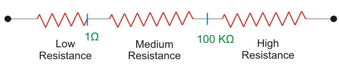
Measurement of Resistance ( FULL UNIT ) LOW &MEDIUM RESISTANCE MEASUREMENT

Measurement of Resistance Resistance is one of the most basic elements encountered in electrical and electronics engineering. The valu...